
How a Grease Separator Supports F&B Industry Drainage and Wastewater Control
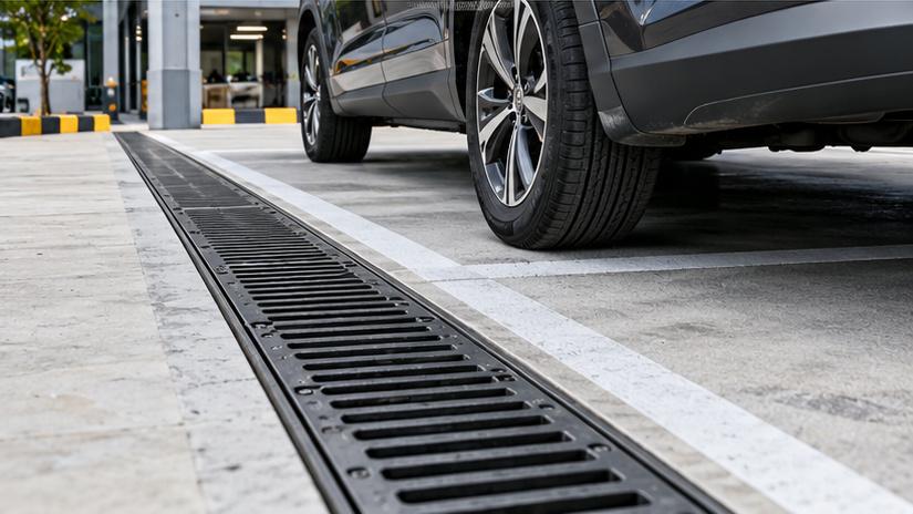
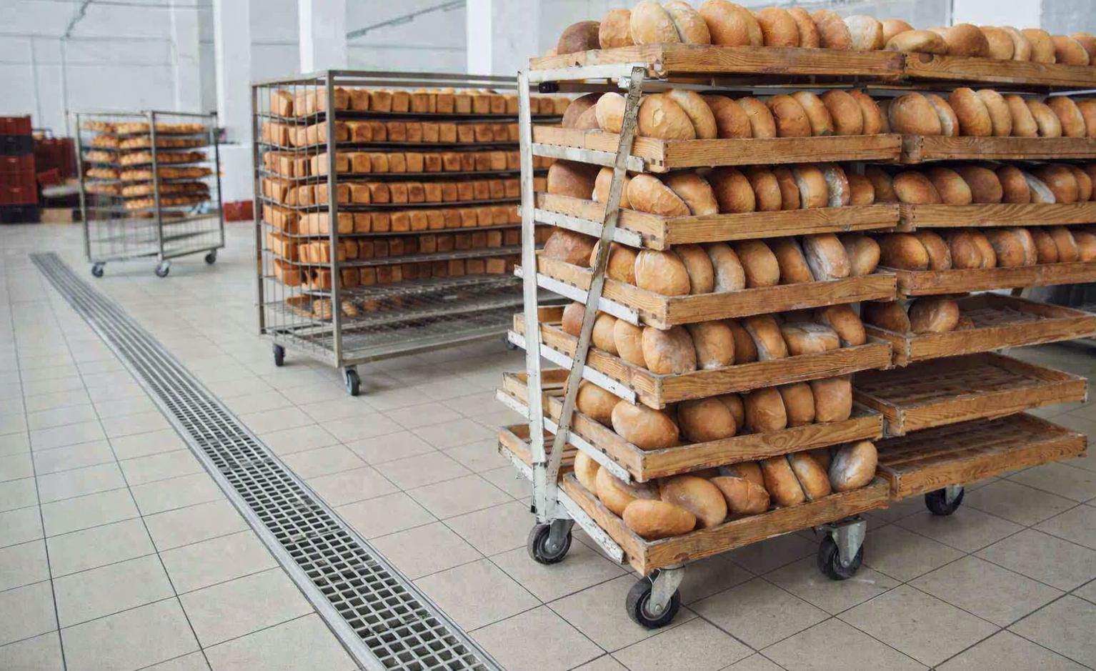
A restaurant may drain normally during service, then back up when sinks and dishwashers discharge together. Hot fats cool on pipe walls, trapping food solids. A Grease Separator Supports F&B Industry drainage only when its flow rating, storage volume and cleaning arrangement match this pattern.
Why Kitchen Drains Block Despite Having a Grease Trap
FOG (fats, oils, and grease) are washed down the drain during cookware washing, food prep, and equipment cleaning. Cooling and depositing of grease restricts flow in the pipe and obstructs it. Repeated blockages may indicate inadequate pipe cleaning.
• Peek Flow Overload: More fixtures than the separator’s inlet rated flow are used at the same time.
• Grease/Sludge Saturation: Waste accumulation decreases storage space, obstructs water movement and causes disruption.
• Emulsified Oil: Detergents break grease into tiny droplets so small they cannot be effectively separated by gravity.
• Incorrect Connections: Grease laden discharge bypasses the unit, or the unit receives wastewater that is incompatible with the unit.
What Actually Separates Grease from Wastewater?
Inside a gravity separator, flow is slowed and distributed. Dense food particles settle into a sludge zone; buoyant, separable oil droplets rise and form a surface layer. The outlet arrangement draws from below that layer.
Hydraulic retention time (HRT) is approximately effective water volume divided by flow. At twice the flow, nominal HRT halves if working volume remains unchanged.
Internal hydraulics matter: short-circuiting can carry grease through a large tank. Detergents may stabilize oil-in-water emulsions; conventional separators cannot reliably remove dissolved organics or stable emulsions. Such loads may require additional treatment.
Gravity, Hydromechanical or Full-Disposal Equipment?
| Approach | Design Strength | Engineering Trade-Off |
| Gravity separator | Passive separation and dedicated grease/sludge storage | Space, access and scheduled emptying |
| Hydromechanical interceptor | Rated hydraulic control in a compact installation | Flow and certified grease-retention limits |
| Automatic grease-removal unit | Mechanically transfers collected grease | Electrical and mechanical maintenance |
| Full-disposal separator | Integrates cleaning, agitation and pumped waste evacuation | Waste-receiving connection, controls and servicing |
Full disposal does not mean maintenance-free. Pumped removal changes how accumulated waste is handled; it does not remove the need to inspect internal chambers, dispose of waste lawfully or verify effluent quality.
Size for Simultaneous Discharge, Not Kitchen Floor Area
For installations designed under EN 1825-2, the calculated nominal size follows:
NS = Qs × ft × fd × fr
Here, Qs is maximum wastewater flow (L/s); ft, fd and fr respectively adjust for temperature, grease density, and cleaning/rinsing agents.
Select an available rated size above the calculated requirement according to the applicable method. This EN sizing approach should not be imposed on every North American hydromechanical interceptor.
An example: Qs = 2.0 L/s and detergent factor = 1.3, with the other factors at 1.0, produce NS = 2.6—not NS 2. Confirm the project-specific factors before selecting a unit.
Two capacities need separate checks:
• Hydraulic capacity: Can the equipment accept the actual peak flow without excessive carryover?
• Grease and sludge storage: How much separated waste can accumulate before evacuation is required?
F&B ApplicationDominant Design QuestionRestaurant or hotel kitchenHow many wash fixtures discharge at once?Central kitchenDoes a concentrated post-service washdown drive peak flow?Meat or food processingAre fats, heavy solids or stable emulsions unusually concentrated?

Pipe Routing and Cleaning Access Determine Operating Reliability
Before Installation
Identify grease-producing sinks, dishwashers and floor drains; trace which are permitted to connect under local plumbing rules. Check inlet/outlet invert levels, DN sizes, venting, hydraulic losses and upstream pipe runs.
For underground units, consider groundwater, structural loads and pump-out access; above-ground equipment needs floor support and clearance. Stainless steel and HDPE also require different corrosion, temperature and load checks.
During Operation
Inspect grease and sludge layers, remove debris, clean accessible surfaces and test any agitator, cleaning pump or discharge pump.
Set cleaning intervals from observed loading and local requirements, not a generic number of days.
Record removed quantities, abnormal flow, pump faults and disposal destinations. Keep collected waste out of any outlet not approved to receive it.
What Standards and Measurements Establish Compliance?
• EN 1825-1: Design and testing of gravity separators.
• EN 1825-2: Selection, installation and maintenance of gravity separation equipment.
• ASME A112.14.3/CSA B481.1: Hydromechanical grease interceptors.
• ASME A112.14.4/CSA B481.5: Grease-removal devices.
Local plumbing and sewer regulations: Installation, discharge and disposal of FOG.
Request model-specific evidence—not a generic claim of certification. Where discharge sampling is required, document the flow and operating state alongside influent/effluent oil-and-grease results.
Lower FOG does not automatically establish compliance with COD or other pollutant limits.
What CMSA Buyers Should Check on a Full-Disposal Unit
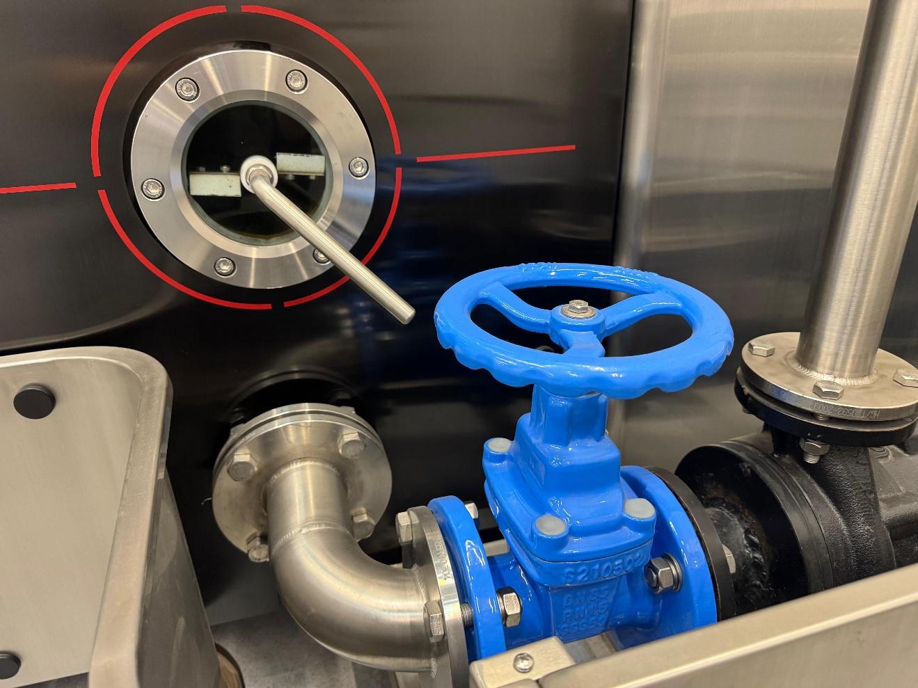
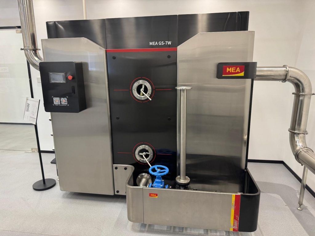
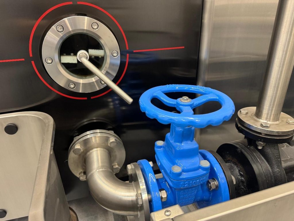
The MEA® GS-2W Full Disposal Grease Separator Unit combines enclosed separation with an agitator, integrated cleaning device and manual/automatic control.
The specification includes:
| Specification | CMSA GS-2W |
| Nominal size | 2 L/s |
| Overall volume | 745 L |
| Construction | Stainless steel |
| Inlet / outlet / vent | DN100 |
| Inspection | Dual grease/sludge sightglasses |
| Maintenance access | 400 mm manhole |
| Waste evacuation | DN65 cutting-vane disposal pump |
Overall tank volume must not be mistaken for effective separation volume or grease-storage capacity.
Confirm that agitation occurs as intended during cleaning rather than disturbing normal separation. The waste pump needs an approved receiving arrangement—not a return to the sewer.
Procurement Checklist for F&B Projects
Before purchase, request:
• Peak-flow sizing calculation and connected-fixture schedule.
• Verified grease/sludge capacity, drawings and maintenance clearances.
• Pump duty, electrical requirements, waste routing and commissioning instructions.
• Applicable test evidence, service provisions and estimated cleaning/disposal costs.
Facilities interested in consolidating grease waste and separation, consider CMSA’s GS-2W Full Disposal Grease Separator Unit in line with the actual wastewater profile and site plan.
That is how a Grease Separator Supports F&B Industry drainage in practice: through defensible sizing and workable maintenance.
FAQs
Q1. How Does a Grease Separator Support the F&B Industry?
A: CMSA grease separators capture separable fats, oils, grease, and settled solids before wastewater enters downstream drainage pipes, helping reduce blockage risks.
Q2. What Is the Nominal Flow Capacity of CMSA’s GS-2W Grease Separator?
A: The CMSA GS-2W has a nominal size of 2 L/s and an overall volume of 745 L. Actual suitability depends on wastewater flow and application conditions.
Q3. What Makes CMSA’s Full-Disposal Grease Separator Different?
A: The GS-2W integrates grease separation, agitation, cleaning, and pumped waste evacuation in one enclosed stainless steel unit.
Q4. Can CMSA’s Grease Separator Remove Emulsified Oil?
A: The GS-2W is designed for grease separation, but stable emulsified oils may require additional treatment. Wastewater characteristics should be evaluated before selection.
Q5. How Does CMSA’s GS-2W Discharge Collected Grease and Sludge?
A: The GS-2W features an integrated cleaning system and a DN65 cutting-vane disposal pump. Removed waste must enter an approved collection or disposal arrangement.


