
Project Reference: G15 Shenhai Expressway Drainage System Application
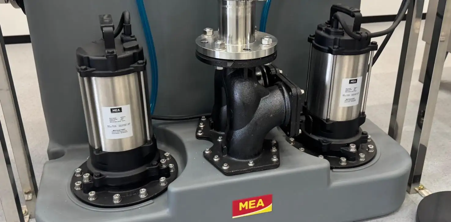
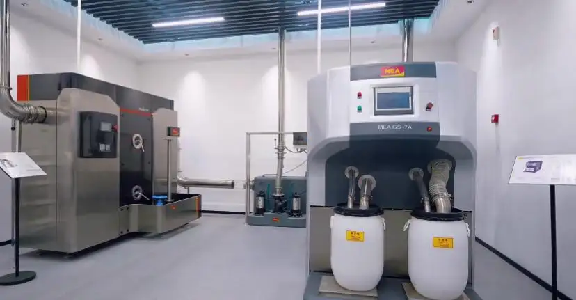

The G15 Shenhai Expressway is a national north–south trunk route connecting Shenyang and Haikou. China's national road network plan identifies major control points including Dalian, Yantai, Qingdao, Shanghai, Ningbo, Fuzhou, Shenzhen, Guangzhou, Zhanjiang, and Haikou. Its extensive coastal alignment means that rainfall criteria, terrain, road width, gradients, and discharge conditions vary significantly between sections.
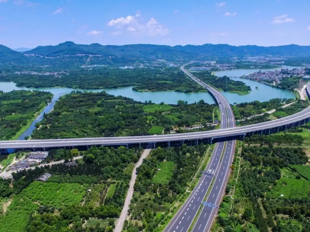
Published project data illustrate the engineering scale. The Nan'cun–Qingdao/Rizhao boundary widening section is 131.45 km long and designed as an eight-lane expressway with a 120 km/h design speed. The Ningbo section extends 69.055 km, also uses eight lanes, and includes 41–42 m roadbeds with design speeds of 100–120 km/h. The Haikou section is 13.727 km long, with six lanes, an 80 km/h design speed, and a 33.5 m roadbed. These differences show why the G15 Shenhai Expressway cannot rely on one channel size or fixed outlet spacing for every section.
Drainage Conditions Behind the Design
Wide expressway pavements create large impermeable catchments. On an eight-lane section with a roadbed up to 42 m wide, even a relatively short drainage reach can receive substantial runoff.
Traffic loading is another important factor. Published information for the G15 Rizhao section reported approximately 20,000–30,000 vehicles per day, with holiday traffic reaching as high as 100,000 vehicles. This level of use places repeated dynamic loads on channels, gratings, edge frames, and surrounding pavement.
The G15 Shenhai Expressway drainage system therefore needed to address:
• Rapid runoff from wide paved surfaces
• Dynamic wheel loads and maintenance vehicles
• Low points, ramps, transitions, and changing gradients
• Restricted construction depth and outlet positions
• Sediment, leaves, tyre debris, and road dust
• Safe access for inspection and cleaning
Design Inputs for Each Drainage Reach
The route must be divided into individual hydraulic catchments rather than treated as one continuous channel run.
| Design Input | Engineering Influence |
| Local rainfall intensity | Defines the design inflow |
| Catchment width and length | Determines runoff volume |
| Road crossfall | Directs water toward the collection line |
| Longitudinal gradient | Controls channel flow direction and velocity |
| Pavement elevation | Sets the channel top level |
| Traffic load | Determines channel, cover, and fixing requirements |
| Outlet depth and position | Controls discharge spacing and connection type |
| Maintenance access | Defines inspection and cleaning points |
Because the G15 Shenhai Expressway crosses several climate regions, rainfall intensity must be taken from the applicable local standard and exact project location. Using one rainfall value for the entire corridor would be technically misleading.
Why Linear Drainage Was Appropriate
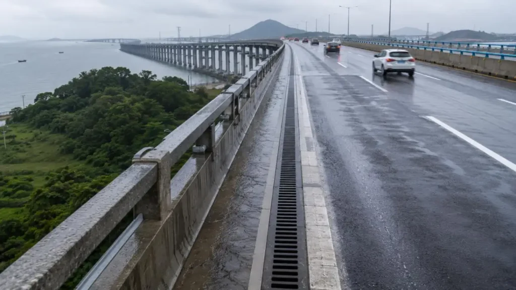
Linear drainage continuously intercepts runoff along a kerb, shoulder, median, bridge edge, or paved boundary. For the G15 Shenhai Expressway, this reduces the distance water travels across traffic surfaces and limits dependence on widely spaced point inlets.
Its main functions include:
• Continuous collection along long road sections
• Faster interception at pavement edges and low lines
• Modular adjustment to changing installation depths
• Multiple connections to underground stormwater pipes
• Coordination with finished pavement elevations
• Removable access for inspection and cleaning
The channel is only one element. Reliable performance depends on the complete route from pavement surface to inlet, channel, outlet, connecting pipe, and final discharge point.
Hydraulic Design: Three Linked Capacities
The G15 Shenhai Expressway drainage design had to balance three connected capacities:
| Capacity | Design Question |
| Inlet capacity | Can runoff enter before ponding develops? |
| Channel capacity | Can the channel convey the accumulated flow? |
| Outlet capacity | Can water discharge without backing up the channel? |
Channel width and depth alone are insufficient. Engineers must also evaluate:
• Inlet opening area
• Internal channel surface
• Longitudinal fall
• Outlet diameter
• Outlet spacing
• Increasing flow along each channel reach
Additional outlets are required where a long run would otherwise exceed the channel or connecting pipe capacity.
Load, Structure, and Material Selection
Published G15 projects use six- or eight-lane expressway standards, with representative roadbed widths ranging from 33.5 m to 42 m. The drainage components must therefore resist wheel loads, impact, vibration, settlement, and construction traffic.
Structural design covers:
• Channel-body strength
• Grating or slot-cover capacity
• Positive locking devices
• Concrete base and lateral encasement
• Joint alignment and edge protection
• Integration with the pavement structure
Channel Falls and Outlet Planning
Depending on the road profile, the drainage system may use:
• Natural ground fall: following the existing road gradient
• Built-in channel fall: using progressively changing channel depths
• Stepped fall: introducing level changes between channel sections
Outlet positions must match the catchment flow, underground pipe location, available depth, and maintenance access. Excessively long distances between outlets can cause water to accumulate even when the channel itself appears adequately sized.
This need for coordinated outlet planning, hydraulic capacity, and installation control provides the engineering basis for CMSA's integrated highway drainage design approach.
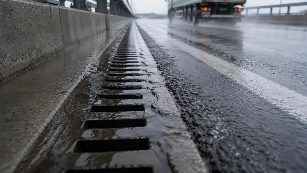
What Makes CMSA's Highway Drainage Design Distinctive?
For the G15 Shenhai Expressway, drainage performance depends not only on channel strength but also on how the hydraulic layout, pavement interface, outlet configuration, and construction process are coordinated. CMSA's engineering approach combines MEA®TRAFFIC drainage components with hydraulic calculation, system layout, BIM support, and installation guidance.
CMSA takes a holistic approach for drainage channels, considering the entire drainage path from surface interception to sub-surface outfall.
A Channel for Heavy Traffic Applications
The MEA®TRAFFIC D/DM Series was developed for use in heavily trafficked, dynamic, asphalt and concrete, road, and pavement applications. The channels feature a fully monolithic design for added structural strength. In addition, the modular channel design allows for flexibility in slope and construction depth.
The system is suitable for traffic-intensive applications such as:
• Expressways and major roads
• Urban tunnels and intersections
• Airport pavements
• Logistics parks and freight yards
• Container handling areas
• Test tracks and transport terminals
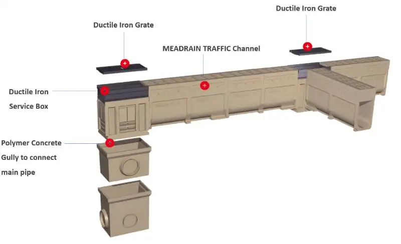
Key Engineering Characteristics
| Design Feature | MEA®TRAFFIC D1000 Specification | Relevance to Highway Drainage |
| Clear channel width | 100 mm | Provides a defined hydraulic section for continuous runoff conveyance |
| Total channel width | 154 mm | Supports integration within restricted pavement and edge zones |
| Adjustable height | 250–350 mm | Allows coordination with installation depth and underground pipe elevations |
| Channel length | 1,000 mm modular units | Simplifies transportation, setting-out, and phased installation |
| Fall configurations | Linear fall, 2.5% stepped fall, or no fall | Adapts the system to flat, sloping, and changing road profiles |
| Load classes | A15–F900 | Supports configurations ranging from pedestrian areas to heavy-duty traffic zones |
| Outlet design | Integrated outlet connector | Improves flow transition and simplifies connection to the drainage network |
The final load class must be selected according to the actual installation position, traffic exposure, pavement structure, and applicable project standards.
Balancing Hydraulic Performance and Structural Strength
The distinctive feature of the CMSA design approach is the coordination of three project requirements:
• Rapid surface interception: The placement of the channel and the openings at the surface are designed to capture surface runoff before it crosses the traffic lane.
• Internal flow: Smooth channel surfaces and falls that can be set at various heights minimize the energy loss due to hydraulic resistance.
• Structural integrity: The channel body, cover, lock, base, and side concrete containment are all designed to be part of a supporting system.
Engineers are able to set channels at different heights to design the system at the desired level with the pavement, while still accommodating the existing services and constraints such as buried services, utility pipes, and drainage outlets.
Design Support from Calculation to Completion
CMSA provides engineering support for the duration of the project, in addition to their drainage product.
Hydraulic and Product Selection
• Use professional drainage software to calculate runoff and channel capacity
• Generate hydraulic calculation reports
• Determine channel dimensions, fall arrangements, outlet and load class, and slot and grating covers
Layout and BIM Coordination
• Perform drainage layout and product-detail drawing preparation
• Provide BIM product families and drawing support to ensure design compatibility
• Verify and ensure compatibility with pavement, piping, and structural and construction elements
Installation and Quality Control
• Provide construction and drainage installation guidance
• Assist and provide support for channel alignment, elevation, jointing, and encasement
• Perform installation support and assist in the acceptance process
The nature of the drainage design for the G15 Shenhai Expressway is that various factors can change for unconnected lengths of drainage, including road width, gradient, and traffic load. Each unconnected length of drainage can be designed to suit the specific Hydraulic and Structural requirements, while still maintaining a unified system throughout the works.
Key Lessons from the G15 Shenhai Expressway
The G15 Shenhai Expressway demonstrates why linear drainage must be designed section by section. Road width, local rainfall, catchment geometry, traffic loading, installation depth, channel capacity, and outlet spacing must operate as one coordinated system.
CMSA supports infrastructure projects with polymer concrete linear drainage solutions, including channel selection, load configuration, fall options, outlet planning, modular layouts, and installation guidance. For more applicable system recommendations, project teams provide road drawings, dimensions of the catchment, criteria pertaining to rainfall, load requirements, installation depths, and locations of outlets.
FAQs
Q1. What are the main specifications of the MEA®TRAFFIC D1000 channel?
The MEA®TRAFFIC D1000 channel features a clear width of 100 mm, a total width of 154 mm, an adjustable height of between 250 and 350 mm, modular 1,000 mm sections, and an integrated outlet connector.
Q2. Why is MEA®TRAFFIC suitable for expressway drainage?
MEA®TRAFFIC is suitable for drainage of expressways and other roadways because it is designed for asphalt and concrete pavements that are subject to constant and dynamic loads. It is structurally stable while allowing channel fall and outlet configurations.
Q3. What drainage calculations can CMSA provide?
CMSA can provide drainage calculations for the delineation of catchment areas, design rainfall, inlet and outlet blockage, channel conveyance, and flow accumulation and can provide reports to document the calculations.
Q4. What information does CMSA need for channel selection?
The roadway design including the catchment area, the design rainfall, pavement slope, installation depth, traffic, outlet, and underground drainage pipe diameters should be provided.
Q5. What load classes are available for MEA®TRAFFIC channels?
MEA®TRAFFIC channels can meet drainage requirements of load classes A15 to F900. The selection of the class should be based on the expected traffic, the position of installation, the thickness of the pavement, and the relevant regulations.


