
Polymer Concrete Trench Drain Solutions for Smart City Stormwater Management
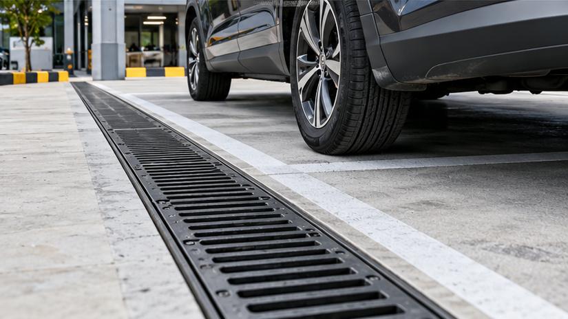
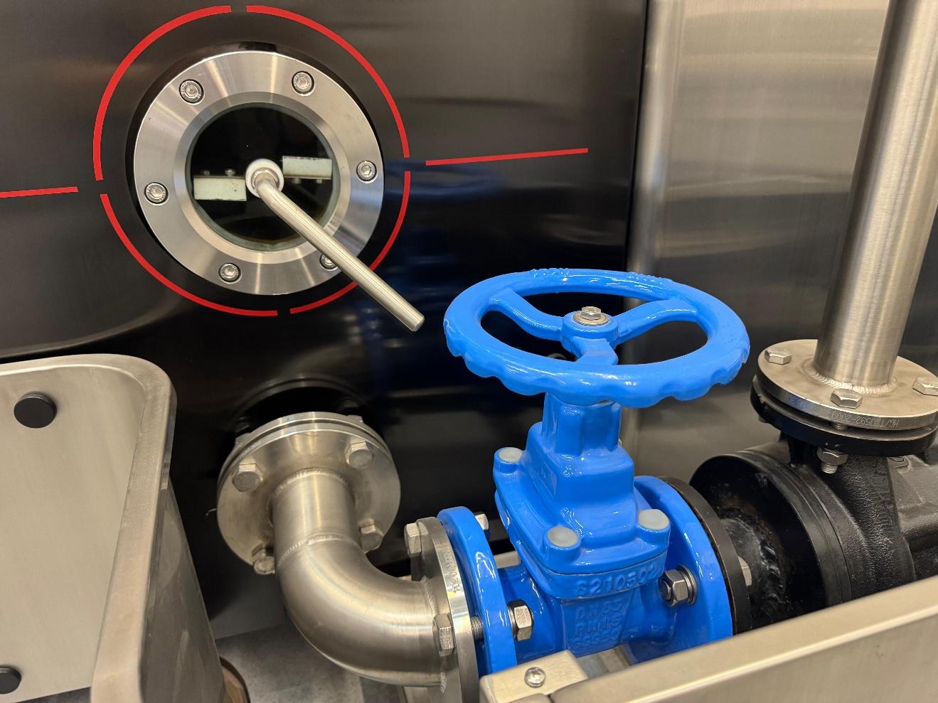
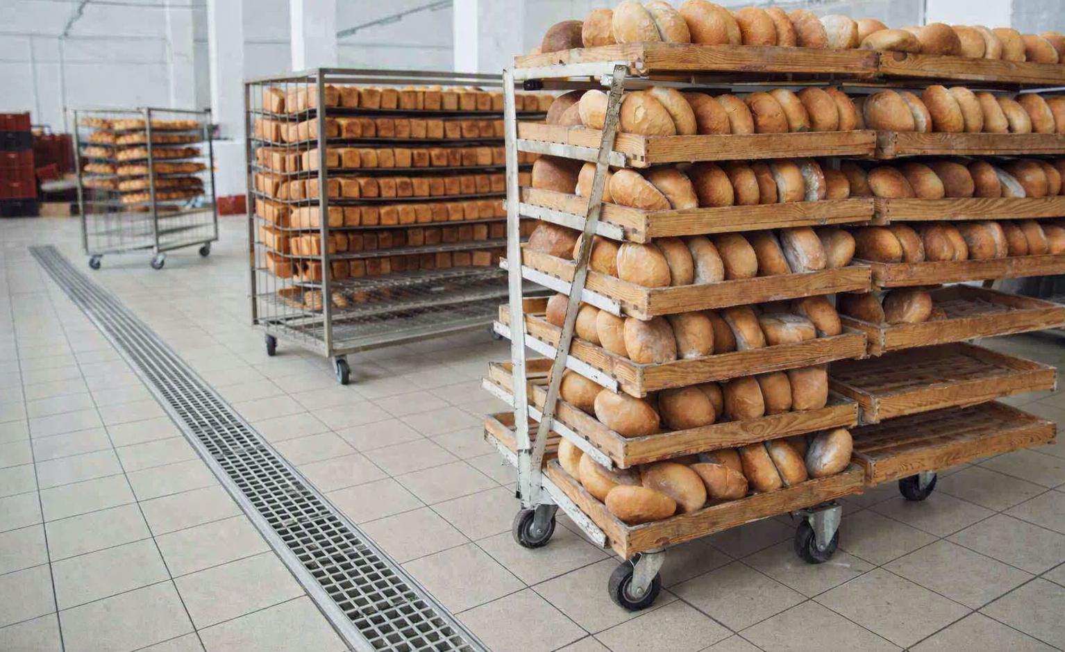
Polymer Concrete Trench Drain Solutions operate continuously to intercept surface runoff. Effective drainage requires more than sufficient channel strength. Inlet geometry, hydraulic capacity, load classification, tolerance, and accuracy of installation, as well as downstream discharge must also be considered.

Why Smart Cities Need More Resilient Drainage Infrastructure
Stormwater runoff from impervious surfaces converges more quickly than from landscaped surfaces. At road intersections and junctions, public squares, and underground ramp basements, concentrated surface runoff can quickly saturate drainage systems, resulting in street flooding.
Other systems that further increase the risk include blocked gratings, undersized outlets and downstream sewer backwater.
Surface water collection using linear, continuous, intercepting drainage solutions is provided by Polymer Concrete Trench Drain Solutions. Compared to point drains, which capture surface water in localized low-lying areas, trench drains capture surface water in a defined drainage line. Neither of these drainage systems is able to prevent flooding if the downstream drainage system is overloaded. To effectively manage drainage for a smart city, the collection, conveyance, storage and controlled discharge systems should be integrated.
How Polymer Concrete Trench Drain Solutions Work
Compared to conventional Portland cement, polymer resin cures more quickly and forms a denser, lower-absorption structure. As such, it is better suited for drainage channels to convey water.
Other advantages include:
• Chemical Resistance: Formulated to provide resistance to chemicals, road salts and moisture.
• Hydraulic Roughness: Formulated to be smoother than other cements. This reduces energy loss due to friction as water flows through it.
• Structural Stability: Formulated to support loads.
• Modular Construction: Sections can be joined together to create longer channels.
While performance is generally good, variations may occur due to type of resin and load conditions.
Surface Water Interception vs. Channel Conveyance
A trench drainage system performs two separate hydraulic functions:
- Interception capacity: The grating or slot must allow the surface runoff to enter without excessive bypass.
- Conveyance capacity: The channel and the outlet network must transport the captured water without a surcharge.
Smoothing walls does not prevent sediment from building up. Important factors in channel design like slope, flow, sediment load and maintenance access are not affected by wall changes.
Hydraulic Design and EN 1433 Load Classification
Calculating Drainage Capacity
For preliminary design, engineers use the Rational Method to estimate peak runoff as:
Q = 0.00278 × C × i × A
Where:
• Q = Peak runoff flow in m^3^/s
• C = Runoff coefficient
• i = Design storm intensity in mm/h
• A = Size of catchment in hectares
Catchment and local design conditions dictate the method’s applicability.
Other design considerations include the channel’s clear width, flow depth and the hydraulic gradient, the inlet and outlet spacings, and the downstream water levels.
In the case of more developed urban areas, integrated models such as the SWMM, offer improved performance in runoff, surcharge and backwater conditions as well as storage.
Selecting the Correct Load Class
EN 1433 establishes load classifications for drainage channels installed in pedestrian and vehicular areas.
| Load Class | Test Load | Typical Application |
| A15 | 15 kN | Pedestrian and cycling areas |
| B125 | 125 kN | Footways and private parking |
| C250 | 250 kN | Kerbside drainage |
| D400 | 400 kN | Road carriageways |
| E600 | 600 kN | Industrial and port areas |
| F900 | 900 kN | Exceptional wheel-load areas |
A higher classification does not automatically produce a better drainage design.
Load selection must account for wheel loads, traffic movement, grating retention, foundation conditions, and the manufacturer’s specified installation structure. Hydraulic capacity and structural loading require independent verification.
Polymer Concrete vs. Conventional Drainage Systems
| Design Factor | Polymer Concrete Channel | Conventional Concrete Channel | Point Drain |
| Water collection | Continuous linear | Continuous linear | Localized |
| Material | Resin-bound aggregates | Cement-based | Varies |
| Layout | Modular prefabricated sections | Precast or cast-in-place | Individual inlets |
| Main limitation | Inlet and outlet capacity | Geometry and joint detailing | Surface grading |
| Typical use | Roads, plazas, paved edges | Larger civil drainage works | Isolated low points |
Polymer Concrete Trench Drain Solutions are not preferable in every application.
Grated channels provide relatively direct inspection access, while narrow slot drains can preserve architectural paving continuity. Slot opening geometry, pedestrian safety, debris characteristics, and cleaning requirements should guide the choice.
Lifecycle evaluation should include material procurement, excavation, installation, cleaning, and eventual component replacement—not purchase price alone.

Integrating Trench Drainage with Smart City Infrastructure
Green Stormwater Management
Polymer Concrete Trench Drain Solutions can connect surface runoff collection with:
• Sediment pretreatment facilities
• Bioretention and rain gardens
• Stormwater detention tanks
• Rainwater harvesting systems
• Controlled discharge networks
Water is primarily carried through concrete-lined channels. Separate infrastructures are required for treatment of pollutants, infiltration and storage.
Infiltration is more suitable in clean and stable soil conditions and where there is no risk of groundwater contamination.
BIM and Smart Monitoring
BIM models assist in the coordination of channel elevations, connection points, and the clearances required for maintenance.
GIS systems help track the location of drainage assets, and dedicated water level and precipitation sensors can aid in the assessment of flood risk.
These digital functions require additional infrastructure, and are not embedded in polymer concrete channels.
Manufacturing Dimensions and Installation Accuracy
At CMSA, we evaluate MEA drainage configurations that incorporate CMSs, mainly based on dimensional compatibility for urban projects.
The product specifications provide useful engineering references:
| MEA Product | Dimensional Specifications | Load Class |
| MEA TopSlot | 100–300 mm clear widths; 1.2, 2, or 3 mm cover-thickness options | Up to D400 |
| MEADRAIN EN3000 | 300 mm opening; 354 mm overall width; 490 mm height; 1,000 mm length | F900, Type M |
These dimensions support channel positioning, pavement integration, and outlet coordination.
Nominal product dimensions should not be confused with verified manufacturing tolerances. For precision-sensitive installations, engineers should request model-specific dimensional tolerances, inspection records, and approved technical drawings.
• Stability of the foundation and specified encasement of concrete
• Alignment of channels and transitions of pavements
• Sealing of joints and connections of outlets
• Gratings and access for inspection
• Sediment removal and storm water drainage
The challenge is to place Polymer Concrete Trench Drain Solutions.
The most reliable specification process is based on a clear sequence:
Assessment of Run-off → Hydraulic Sizing → Load Classification → Installation Design → Technical Verification → Evaluation of Lifecycle
Prior to award, engineers should request hydraulic calculations, load test reports, size and installation and maintenance procedures.
At CMSA, we work in partnership with engineering teams, integrating MEA Drainage Solutions in 3D Designs, providing layout and installation support.
Explore our polymer concrete trench drain solutions and solve the drainage needs of your next smart-city project.
FAQs
Q1. What polymer concrete trench drain solutions does CMSA offer?
CMSA supplies MEA linear drainage systems, including MEADRAIN EN, MEA TopSlot, MEA Kerb Drain, and parking drainage channels for urban infrastructure projects.
Q2. Can CMSA provide drainage solutions for smart city projects?
Yes. CMSA offers drainage products for roads, plazas, parking facilities, and transportation infrastructure, supported by hydraulic design and product selection services.
Q3. Does CMSA provide hydraulic calculations for drainage projects?
Yes. CMSA provides hydraulic calculations using specialized software, helping engineers evaluate channel capacity and select suitable drainage configurations.
Q4. What load classes are available in CMSA’s MEA drainage systems?
The MEADRAIN EN product range covers EN 1433 load classes from A15 to F900. The appropriate classification depends on the specific model and installation requirements.
Q5. Does CMSA offer slot drainage systems for urban landscapes?
Yes. MEA TopSlot drainage offers 100–300 mm clear widths, customizable slot configurations, and load classifications up to D400.


