
Polymer Concrete Drainage for Large-Scale Project: Hydraulic Capacity and Channel Sizing
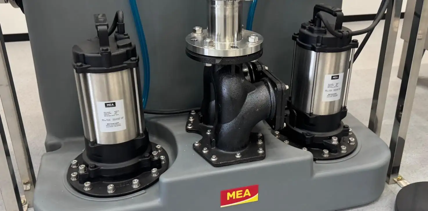
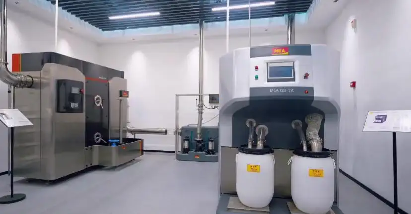

The extensive impermeable surfaces found in large airports, highways, ports, logistics and industrial facilities, and urban infrastructures generate considerable surface runoff. Thus, an effective, large-scale Polymer Concrete Drainage system must be designed considering the runoff from the aforementioned factors, as well as rainfall intensity, the catchment area, channel dimensions, longitudinal slopes, and the performance and capacity of inlets and outlets, respectively.
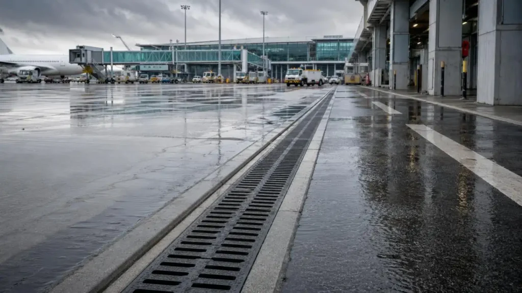
Selecting a channel only by its visible width can result in ponding, traffic hazards, pavement deterioration, and overloaded downstream pipework. Hydraulic capacity and structural load resistance should always be assessed together.
What Is Polymer Concrete Drainage for Large-Scale Project Applications?
Large Scale Project Applications refers to a system that collects and conveys surface water using prefabricated modular linear channels on large sites for civil engineering contracts. Polymer concrete consists of a polymer binder and a mineral aggregate system, resulting in a channel system that is high strength, low water absorption, resistant to chemicals, internally smooth, and modular.
The attributes of the material make it suitable for use in pavements, runways, hardstanding areas, terminals, parking areas, industrial sites, rail, and urban drainage systems.
What Determines the Hydraulic Capacity of a Drainage Channel?
Hydraulic capacity describes how much water a channel can convey without overflowing. Important design parameters include:
•Design rainfall intensity
•Catchment area
•Surface runoff coefficient
•Channel clear width and effective depth
•Longitudinal channel slope
•Internal surface roughness
•Grating or slot inlet capacity
•Outlet diameter and spacing
•Downstream pipe capacity
•Allowance for sediment, debris, and partial blockage
Two separate questions must be answered. First, how much runoff reaches the channel? Second, can the selected channel and outlet arrangement transport that flow safely?
Smooth polymer concrete walls can reduce hydraulic resistance and sediment accumulation. True capacity must still be validated with hydraulic calculations.
How Is Runoff Calculated for a Large Infrastructure Project?
For many drainage areas, engineers begin with the Rational Method:
Q = C × I × A
Where:
•Q is the design runoff flow
•C is the runoff coefficient
•I is the design rainfall intensity
•A is the catchment area
Airfield pavements, highways, loading yards, and concrete plazas generally have high runoff coefficients because little rainfall infiltrates the surface.
Rainfall return periods must be determined considering local guidelines, the expected project risk, the importance of the project, and the anticipated impact of flooding. The same units must be used throughout the calculations.
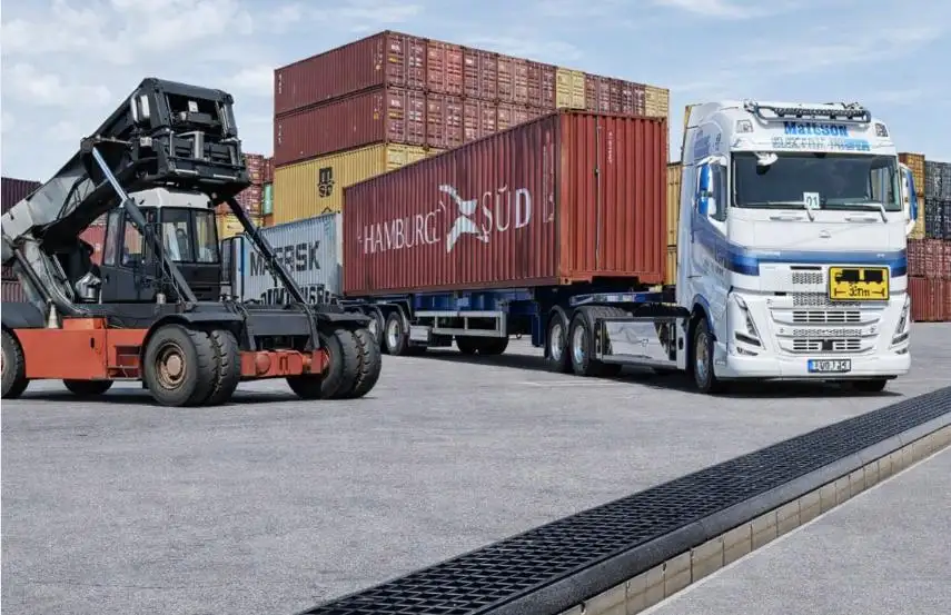
The Rational Method will determine how much runoff will flow to the drainage system, whereas the calculations for the channel's hydraulics will determine if the chosen channel can safely pass the flow. Manning's equation will be used with professional drainage software to aid in the evaluation of flow area, hydraulic radius, slope, velocity, and channel roughness.
How Are Channel Width and Depth Decided?
Channel depth and width both significantly impact channel capacity. While a channel with greater width or depth can convey greater flow, the depth of channel construction, the level of the outlets, utility conflicts, and the pavement structure must also be taken into account.
| Clear Width | Typical Application Direction | Main Design Check |
| 100 mm | Pedestrian areas, road edges, local catchments, small parking zones | Inlet efficiency and outlet spacing |
| 150–200 mm | Roads, parking areas, transport hubs, industrial sites | Flow capacity under medium or high runoff |
| 300 mm | Airports, ports, logistics yards, large paved areas | High flow, heavy loading, and outlet capacity |
| 400–500 mm | Concentrated drainage lines and very large catchments | Installation depth, downstream capacity, and maintenance access |
Width of a channel combined with other factors such as depth, slope, inlet and outlet spacing, and downstream capacity determines the hydraulic performance.
How Channel Slope and Internal Fall Impact Flow Capacity?
A drainage system can utilize a channel with no internal fall, a channel with linear internal fall, or a channel with stepped internal fall.
A linear fall will lower the channel invert gradually and can increase flow velocity. A stepped fall will create a series of channel sections of increasing depth, generating hydraulic progression over a longer distance. A no-fall channel can also work effectively, within site level constraints, if the channel depth, outlet spacing, and design flow are correct.
More slope is not always ideal. Flow with higher velocities can increase the discharge forces at the outlets and can cause damage to the pipework downstream. When assessing the performance of the channel the flow capacity, self-cleansing characteristics, depth of excavation and outlet conditions should be taken into consideration.
Why Must Inlet and Outlet Capacity Be Checked Separately?
A large channel can still overflow when water cannot enter through the grating or slot quickly enough. Inlet performance depends on:
•Grating open area
•Slot width
•Crossfall and surface gradient
•Surface water velocity
•Debris accumulation
The capacity of outlets must be checked separately. Even if the channel body is sized properly, small outlet pipes, excessive outlet spacing, poor outlet connections, and inadequate outlet capacity may all cause a hydraulic bottleneck.
•Local sag points
How EN 1433 Load Class Affects Selection?
A Polymer Concrete Drainage for Large-Scale Project must withstand both hydraulic demand and traffic loading.
| EN 1433 Class | Typical Application |
| A15 | Pedestrian and landscaped areas |
| B125 | Driveways and light parking areas |
| C250 | Kerb zones and low-speed traffic areas |
| D400 | Public roads and commercial traffic areas |
| E600 | Industrial sites and heavy vehicle routes |
| F900 | Airports, ports, container terminals, and extreme loads |
Load class should be selected according to the channel's exact installation position. Not every drain within a large project requires the highest class.
Common Hydraulic Sizing Mistakes
Common errors include selecting only by clear width, treating the entire site as one catchment, using excessive outlet spacing, ignoring blockage allowances, overlooking road crossfall, and failing to verify downstream pipe capacity.
A better approach is to divide the site into hydraulic zones, calculate peak runoff for each area, confirm inlet capture, check channel capacity, and coordinate every outlet with the underground drainage network.
CMSA's Solutions for Varying Project Conditions
CMSA provides support for the design of Polymer Concrete Drainage for larger projects using MEA systems for different conditions of hydraulics, structures, and architecture.
| Project Requirement | MEA System | Main Selection Features |
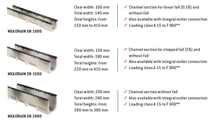
| Large flow and heavy loading | MEADRAIN® EN | Clear widths from 100–500 mm with multiple options for falls, load classes from A15–F900 |
| Roads and traffic areas | MEA® Traffic D/DM | Monolithic construction with an outlet connection, load classes from A15–F900 |
| Airports and ports | MEADRAIN® Supreme EN3000 | Opening of 300 mm, with ductile iron grating and cast iron edges, F900 Type M |
| Urban kerb drainage | MEA® Kerb | Monolithic kerb and drainage channel |
| Architectural slot drainage | MEA® TopSlot | Single, double or curved slots in stainless steel |
| Rail infrastructure | MEA® City Rail | Chemical resistant and rapid discharge of water and debris |
| Parking facilities | MEADRAIN® PG | Designed with an accessible surface for vehicles, bicycles, and wheelchairs |
CMSA assists project teams with hydraulic calculations, selection of channels, layout, detailed product drawings, and outlet integration. Other aspects of technical support may include product families in BIM, multidisciplinary coordination, installation support, site supervision, and support during the final acceptance of the works.
This custom approach allows engineers to make decisions on channel width and depth, fall, load class, grating type, and outlet position as one integrated system.
Closing Words
Designing a drainage system for a large-scale project requires a dependable polymer concrete drainage solution that accommodates the rainfall intensity and catchment and considers channel capacity, inlet and outlet performance, and structural load. CMSA provides support for airports, roadways, terminals, industrial, and city site developments with hydraulics calculations, MEA selection, BIM, drainage layouts, and installation support.
FAQs
Q1. How does CMSA assist with the design of polymer concrete drainage systems?
CMSA assists with the design of polymer concrete drainage systems by providing hydraulic calculations, selecting drainage channels, planning layouts, coordinating outlets, providing product drawings, providing BIM, and offering on-site support.
Q2. Can CMSA determine the required capacity of drainage channels?
Yes. CMSA evaluates rainfall intensities, catchment areas, runoff coefficients and channel slopes, assesses the outlet locations as well as the terminal and downstream conditions to perform project-specific hydraulic calculations.
Q3. For which projects are CMSA polymer concrete drainage systems suitable?
CMSA polymer concrete drainage systems are suitable for airports, highways, ports, terminals, logistics centers, warehousing and industrial facilities, parking areas, rail and transport infrastructure, buildings and urban development.
Q4. What are the channel widths provided by CMSA?
CMSA provides polymer concrete drainage channels as series with clear widths ranging from approximately 100 mm to 500 mm in various layouts and configurations.
Q5. Does CMSA offer F900 heavy duty drainage channels?
Yes. CMSA provides MEA systems of up to EN 1433 Class F900 suitable for challenging applications, including airport apron areas, container terminals, ports, loading docks and heavy haul transport ways.


